2. Kirchhoff’s Voltage and Current Laws
2.1. Objectivec
The objective of this Lab activity is to verify Kirchhoff’s Voltage Law (KVL) and Kirchhoff’s Current Law (KCL) using mesh and nodal analysis of the given circuit.
2.2. Notes
In this tutorials we use the terminology taken from the user manual when referring to the connections to the Red Pitaya STEMlab board hardware. Extension connector pin used as 5V voltage source are show in the documentation here.
Background
Kirchhoff’s Voltage Law states that the algebraic sum of all the voltages around any closed path (loop or mesh) is zero. If we define the voltages across each resistor R1 through R5 as V1 through V5, applying Kirchhoff’s voltage law to the first and the second loops in the circuit shown in figure 1 yields:
Loop 1
Loop 2
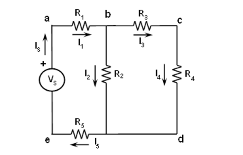
Fig. 2.1 figure 1: Kirchhoff’s Voltage Law
Kirchhoff’s Current Law states that the algebraic sum of all the currents at any node is zero. If we define the currents through each resistor R1 through R5 as I1 through I5, applying Kirchhoff’s current law to the first four nodes in the circuit shown in figure1 yields the following equations;
Node a:
Node b:
Node c:
Node d:
2.3. Materials
Red Pitaya STEMlab 125-14 or STEMlab 125-10
Various Resistors:
1 KΩ (2),
1.5 KΩ (2),
2.2 KΩ
2.4. Procedure
Step 1.
Construct the circuit shown in Figure 1 using these resistor values:
R1 = 1 KΩ
R2 = 2.2 KΩ
R3 = 1.5 KΩ
R4 = 1 KΩ
R5 = 1.5 KΩ
Step 2.
Use color_coding_tool to select correct resistors from your kit. Use Multimeter, resistance measurements to check actual resistor values.
Step 3.
Instead of voltage source “Vs” shown on the Figure 1 use the STEMlab voltage pins on extension connector E2. Connect the 5V pin to node a and connect node e to GND pin.
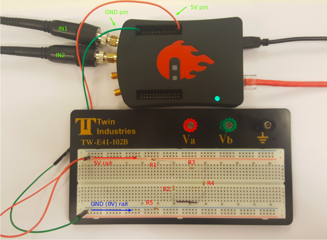
Fig. 2.2 figure 2: Power connections
Circuit on the breadboard is shown in picture bellow.
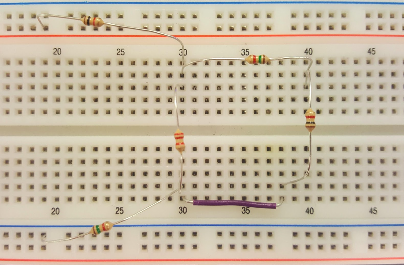
Fig. 2.3 figure 3: Resistors circuit from close
Step 4.
Accurately measure all voltages and calculate currents in the circuit using the Oscilloscope application.
Measuring voltage drop across desired resistor is done in such way that Oscilloscope probe of IN1 is connected to the one side of the resistor and Oscilloscope probe of IN2 is connected to another side of the resistor. Voltage difference VIN1-VIN2 will give an voltage on the measured resistor.
Set probes attenuation to x10
Connect probes to the desired resistor
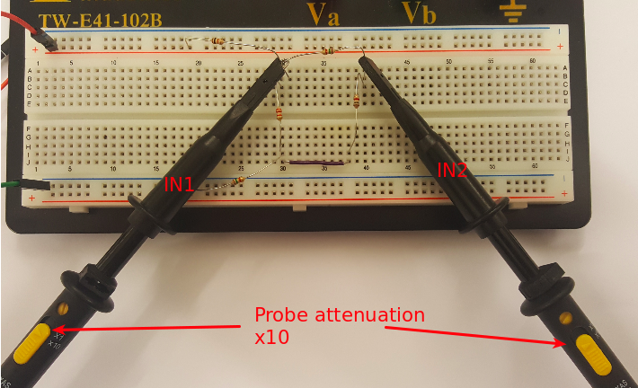
Fig. 2.4 figure 4: Measureing circuit
Start Oscilloscope application
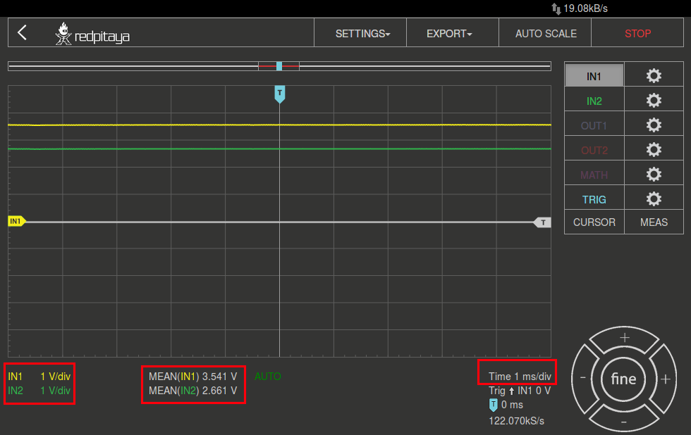
Fig. 2.5 figure 4: Osciloscope application
In the IN1 and IN2 settings menu select Probe attenuation x10
In the measurement menu select “MEAN” , select IN1 and press DONE
In the measurement menu select “MEAN” , select IN2 and press DONE
After clicking “done” the measurements of the mean value of the IN1 and IN2 will be shown. Use this measurement to calculate voltage on R1.
VR1= MEAN( IN1 ) - MEAN( IN2 )
IR1= VR1/ R1.
Note
To obtain correct voltages signes, when performing measurement always work in the same direction: for example, connect IN1 probe on the side of the resistor where marked arrow begins (Figure 1)
Step 5.
Record the measurements in a tabular form containing the measured voltage and current values as shown below.
Branch
current/voltage
V [volts ]
I [mA]
R [KΩ]
V1, I1
V2, I2
V3, I3
V4, I4
V5, I5
Vs,Is
Step 6.
Verify KVL for the loops in the circuit using loop equations 1 and 2.
Step 7.
Verify KCL for the nodes in the circuit using node equations a, b, c and d.
2.5. Questions
Calculate the ideal voltages and currents for each element in the circuit and compare them to the measured values.
Compute the percentage error in the two measurements and provide a brief explanation for the error.